This article outlines the common design procedures used to evaluate the performance of geotechnical systems that are proposed for mitigation of lateral spreading.
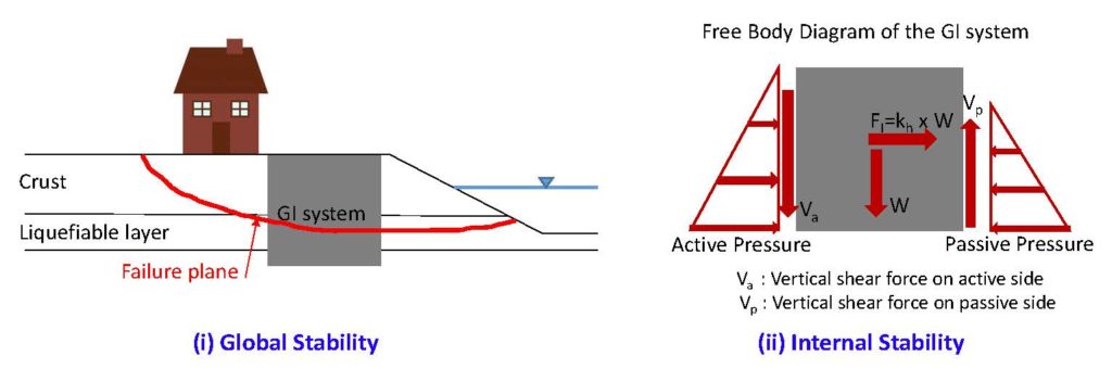
The design of any type of retaining structure generally includes; (i) global stability analysis, and (ii) internal stability analysis. In the former, general mass movement of a retaining structure as well the adjacent soil is evaluated. Limit equilibrium methods of analysis are typically used to determine the global stability. In the latter, i.e., internal stability analysis, a free-body diagram of the retaining structure is developed. All driving and resisting forces are determined, and thereafter potential for overturning, sliding as well as structural damages are assessed. Figure 1 provides further illustration for each step.
Three common scenarios may be encountered when dealing with lateral spread mitigation. These scenarios are listed below and the design items that should be checked for each is elaborated.
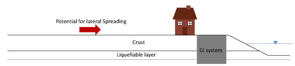
1. Lateral spread mitigation in proximity of a free-face:
As shown in Figure 2 below lateral spread mitigation is required close to a free face. In this scenario, in addition to lateral spread analysis, a slope stability assessment is necessary to check the stability of the slope before and after liquefaction.
The design requirements for this scenario are:
a. Global stability analysis
a.1. Pseudo-static stability assessment before liquefaction: Calculate seismic coefficient k_h per my previous post here. Perform limit equilibrium analysis using the undrained strength of the native soil. Strength loss due to liquefaction should NOT be considered at this stage.
a.2. Static stability assessment after liquefaction: Estimate residual strength of liquefiable soils using the recommendations of Idriss and Boulanger (2008). For ease of access, see section 1.2 in my previous post here. Do not apply seismic coefficient to the limit equilibrium model, i.e., k_h = 0.0 . Note that liquefaction state and peak ground acceleration do not occur simultaneously. There is high level of conservatism incorporated already into prediction of liquefaction triggering, peak ground acceleration (PGA), earthquake magnitude (M), and residual shear strength of liquefied soil
a.3. Static stability assessment for lateral spreading stage: This design item is required if it is judged by the Engineer that the crust in front face of the retaining structure will flow away due to lateral spread. In this case, the crust at the front face would not provide any resistance, and therefore a separate global stability analysis should be performed by removing the crust layer from the limit equilibrium model at front face of the retaining structure.
b. Internal stability analysis
b.1. Stability analysis before liquefaction state: Develop free-body diagram of the retaining structure. Calculate seismic active thrust on the structure using the approach described in my previous post here. Calculate weight and horizontal inertial force applied at the center of gravity of the retaining structure. Calculate static passive pressure in front face of the wall using traditional methods for static loading conditions. Check the followings:
– Factor of safety against overturning;
– Factor of safety against sliding;
– Factor of safety against geotechnical bearing capacity failure at the base of retaining structure;
– Factor of safety against structural crack and crushing at the base of retaining structure.
For the last two items, soil pressure distribution needs to be computed at the base. Please refer to any foundation engineering textbook for calculation of soil pressure and geotechnical bearing capacity.
Further items may be needed to be checked depending on what local design guidelines are used. For example, in case the retaining structure is a deep soil mixing shear key, FHWA Design Manual: Deep Mixing for embankment and foundation support (2013) has further design items to be checked such as racking failure and potential for native soil extrusion through the gap between shear keys.
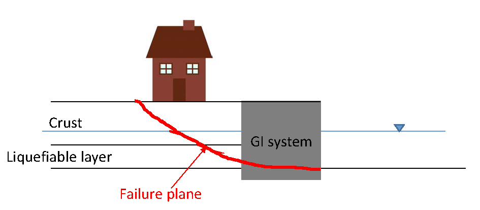
b.2. Stability analysis during lateral spreading: This design item needs to be assessed if it is judged that the slope in front face of the retaining structure would flow downstream. For better illustration, the free-body diagram is shown in Figure 3. Note that no inertial force is induced at the retaining structure because k_h = 0.0. It is conservatively assumed that passive earth pressure is developed within the crust layer at the back face of the retaining structure.

The safety factors listed above should be computed and overturning, sliding, geotechnical and structural bearing capacities should be assessed.
2. Lateral spread mitigation far from a free-face
In this scenario, project site is located far from the free-face, however it is judged by the “Engineer of Record” that there is a high potential for lateral spread. Figure 4 below illustrates this scenario.

The design requirements are:
a. Global stability analysis
Since the free-face is far from project site there is no need to check the free-face slope stability before and after liquefaction. However, if it is judged by the Engineer that the crust in front face of the retaining structure will flow downstream due to lateral spread, it is necessary to perform a slope stability analysis without including the crust in front face of the retaining structure. Seismic coefficient should NOT be applied. Residual strength should be used for liquefiable soils. The residual strength can be determined from my previous post here (section 1.2). Figure 5 showss the ground layout due to lateral spreading of soil in front face of a ground improvement (GI) or any type of retaining systems.
b. Internal stability analysis
Internal stability is performed following the same procedure described in section 1, part b.2.
No further analysis is necessary.
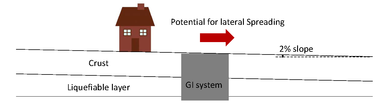
3. Lateral spread mitigation in a sloping ground.
As shown in Figure 6, project site is located in a gently sloped ground. In addition to lateral spread analysis, stability assessment of an infinite slope condition is necessary for before and after liquefaction conditions.
Required design items for this scenario are the same as those listed earlier in section 1.
2 thoughts on “Simplified design methods – Mitigation of lateral spread”
Do you have a suggested limits on the amount of lateral spreading a house on sloping ground can sustain?
John, it depends on the house foundation system (e.g. spread footing, mat, etc). For spread footings, structural engineers may be ok with up to 2 inches of lateral differential movements of footings. When the estimated movement is in the range of 6 inches or more, structural engineer may have to design mat and make the utilities flexible to sustain the deformations during the design earthquakes.
Hope this answered your question.