Introduction
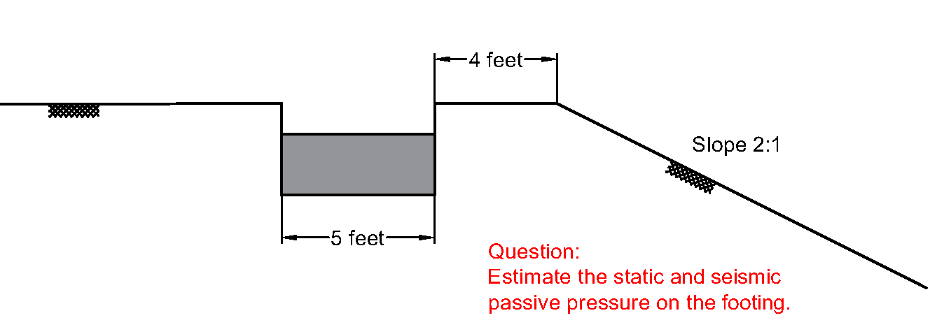
The current state of practice adopts Rankine/Coulomb theory to estimate static passive pressure and Mononobe-Okabe (M-O) method to determine seismic passive pressure. As you know, each of these approaches were formulated based on some assumptions that may not apply to all of our daily engineering problems. For instance, the M-O method was originally developed for dry homogeneous granular backfill so it would not provide reliable estimates of passive pressure for saturated layered soils with interbedded layers of cohesive soils (common soil conditions for design of bulkhead systems). The other example that illustrates the limitations of the Rankine/Coulomb/M-O methods is the case where you need to determine static and seismic passive pressures for a 5-foot wide shallow footing located at a distance of say 4 feet from a 2H:1V slope.
Alternative Approach to Determine Passive Pressure
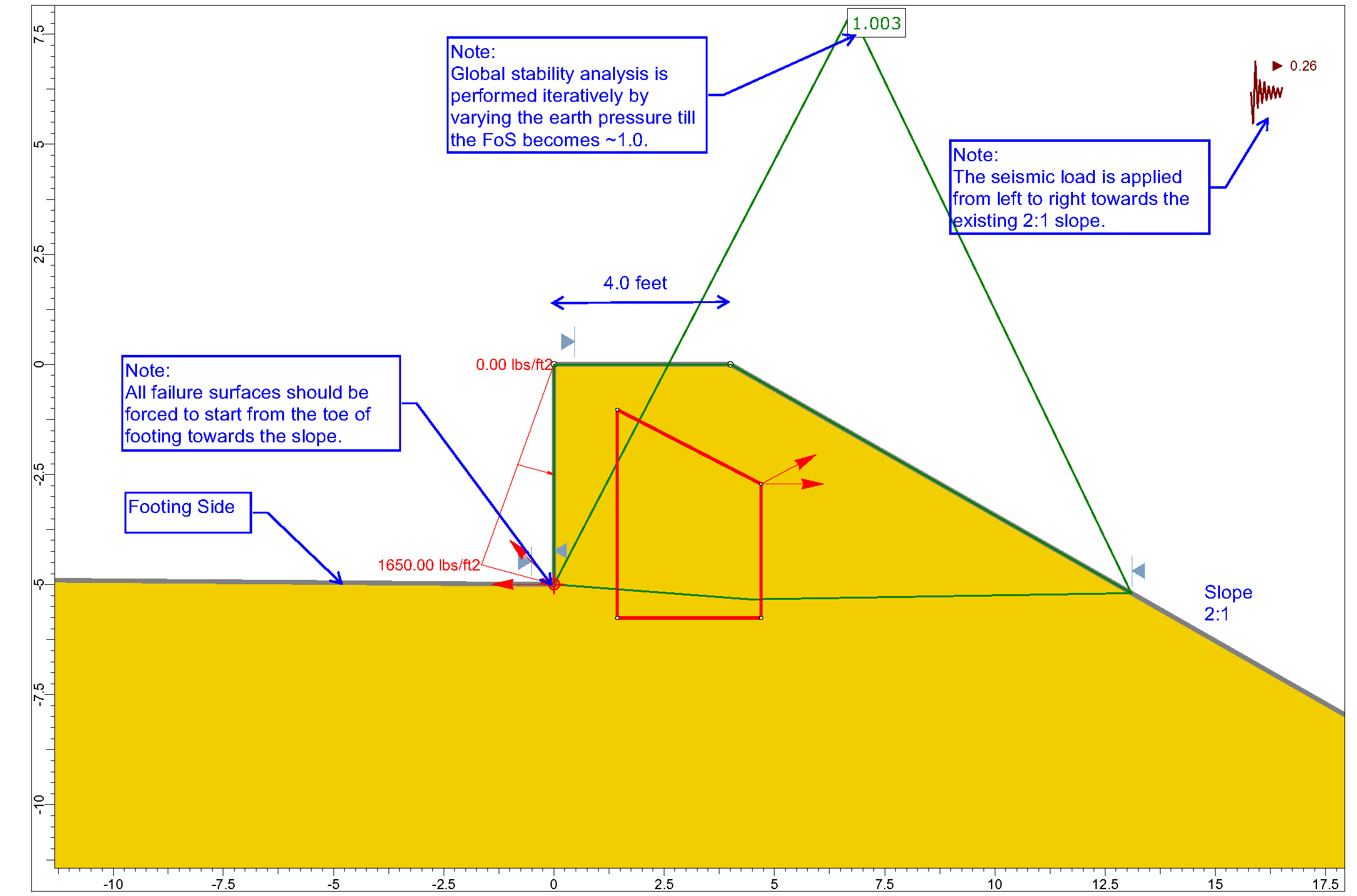
To resolve all the limitations set forth above, an alternative approach is suggested herein. This approach requires performing iterative 2D limit equilibrium slope stability analysis using any of the available commercial software such as SLIDE, SLOPE/W. The analysis procedure is listed below. For clarity, some details of the procedure is depicted in Figure 2.
- Develop a model of retaining structure/footing, soil layers, and slope configuration (if applicable) using computer program SLIDE, SLOPE/W, etc;
- Remove the retaining structure/footing from the model and remove the soil volume in back face (“active” side) of the retaining structure/footing with the same height of the structure. The width of the removed area can be any random value because the goal is just to eliminate shear and normal stresses at the interface of the retaining structure and soil on the “passive” side;
- Define a triangular soil pressure applied in the horizontal direction (see Figure 2 below). The pressure should be applied over the entire height of the retaining structure/footing . Note that the retaining system should be removed from the model. The analysis is going to be conducted iteratively by varying the soil pressure, so for now, use a random pressure say 1000 psf;
- Soil-wall interface friction angle ( \delta ) can be considered by applying the pressure downward with an angle of ( \delta ) from the horizontal plane.
- As shown in Figure 2, define failure plane search box in front of the retaining structure and a single search point at the toe. Other advanced failure surface search tools such as “Cuckoo Search” and “Auto Refine Search” should be also checked to make sure that all potential failure surfaces (planar, log-spiral, composite) are examined. Just those failure surfaces that extend from the toe of the wall to ground/slope surface should be considered as the potential failure surfaces. See Figure 2 for better illustration;
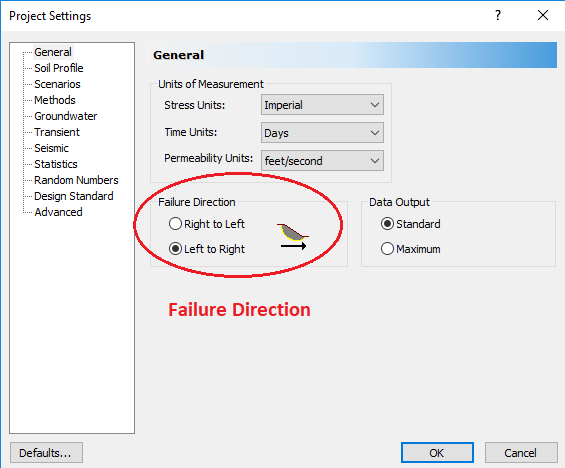
- “Failure Direction” as available in SLIDE program should be set from the wall side towards the front face of wall/footing (see Figure 3 below);
- Perform limit equilibrium analysis iteratively by varying soil pressure (defined in step 3) until factor of safety against failure becomes 1.00. The pressure corresponding to FoS=1.00 is considered as total passive pressure.
Verification
The approach has been verified for simple ground conditions where the Rankine/Coulomb/M-O methods were applicable. Dry soil condition and a level ground with granular soils \gamma = 120 pcf, \phi = 32 \degree, \delta = 0 \degree were considered. Passive earth pressure coefficient ( k_p ) was estimated using both the traditional and the proposed alternative approaches for static and seismic loading condition ( k_h = 0.3g ). Using the traditional methods, static and seismic k_p were estimated to be 3.25 and 2.66, respectively. The alternative approach estimated the same values.
Further Notes
If subsurface conditions consist of several layers. The steps 1 to 7 discussed above should be implemented for each layer in an independent limit equilibrium analysis. The analysis should start off with the shallowest layer (Layer #1) where only the first layer is removed and triangular shape passive pressure is induced within the layer. The analysis of subsequent layer #2 would include removing the soil within layers #1 and #2, and then applying (i) the triangular shape earth pressure of layer #1 which is determined in the previous stage, and (ii) trapezoidal passive earth pressure with magnitude k_{p,2} \sigma'_{v,Top} at the top of layer #2 and k_{p,2} \sigma'_{v,Bot} at the layer bottom. The limit equilibrium analysis would be iteratively performed by varying the magnitude of k_{p,2} . The analysis of layer #3 would include removing the soil within layers #1, #2, and #3, and then applying (i) the triangular shape earth pressure of layer #1 which is determined in the first analysis stage, (ii) the trapezoidal passive earth pressure for layer #2 determined in the second analysis stage, and (iii) trapezoidal passive earth pressure with magnitude k_{p,3} \sigma'_{v,Top} at the top of layer #3 and k_{p,3} \sigma'_{v,Bot} at the layer bottom. Limit equilibrium analysis should be performed iteratively by varying the parameter k_{p,3} . The same procedure can be implemented for the following layers #4, #5, … .
Concluding Remarks
An alternative approach for determination of static/seismic passive pressure is proposed herein. The proposed approach does not have the limitations that the Rankine/Coulomb/M-O methods have. The alternative approach is capable of evaluating:
- any shape of failure surfaces including planar, log-spiral and composite slip surfaces;
- layered soil conditions that consist of c-\phi soils and cohesive soils;
- seismic loading condition, and
- any topography including infinite/finite slopes, excavation, etc.