The current engineering practice adopts the concept of beam on a nonlinear Winkler foundation (BNWF) in order to perform displacement-based analysis on piles, cantilever walls, and bulkhead systems. This post provides an OpenSees TCL file to develop the BNWF model of a beam supported on a series of nonlinear springs. Similar to other OpenSees TCL files available in this weblog, the TCL code is user-friendly where the user can easily develop the geometry of pile/wall and springs.
Soil-beam interaction is simulated by “MultiLinear” model as available in OpenSees libraries. It is to be noted that unlike a soil-pile model, soil reaction on two opposite sides of the beam would be different in a soil-wall model since one side of the beam would be in “active” state where other side would be in “passive” state. In addition, there is less overburden pressure on the passive side due to excavation, and this would make the passive side spring backbone curve totally different than that on the active side. Unfortunately, a nonlinear spring with two different backbone curves defined in two opposite directions has not been implemented in OpenSees libraries yet. In order to resolve this issue for soil-wall interaction analysis, the TCL code uses the following trick:
Two independent “MultiLinear” models are assigned at a given depth on the leftside and rightside of the beam. Each”MultLinear” spring is in series with a rigid “Uniaxial Elastic – No Tension” material on each side in order to eliminate soil resistance from one side when the beam is pushed to the opposite side. Figure 1 below shows the schematics of the soil-beam model. The backbone curves for the “MultiLinear” model can be determined from the available guidelines such as American Petroleum Institude (API) or from available commercial software such as LPILE.
You can download the tcl file from this link: BNWF Model_TCL File
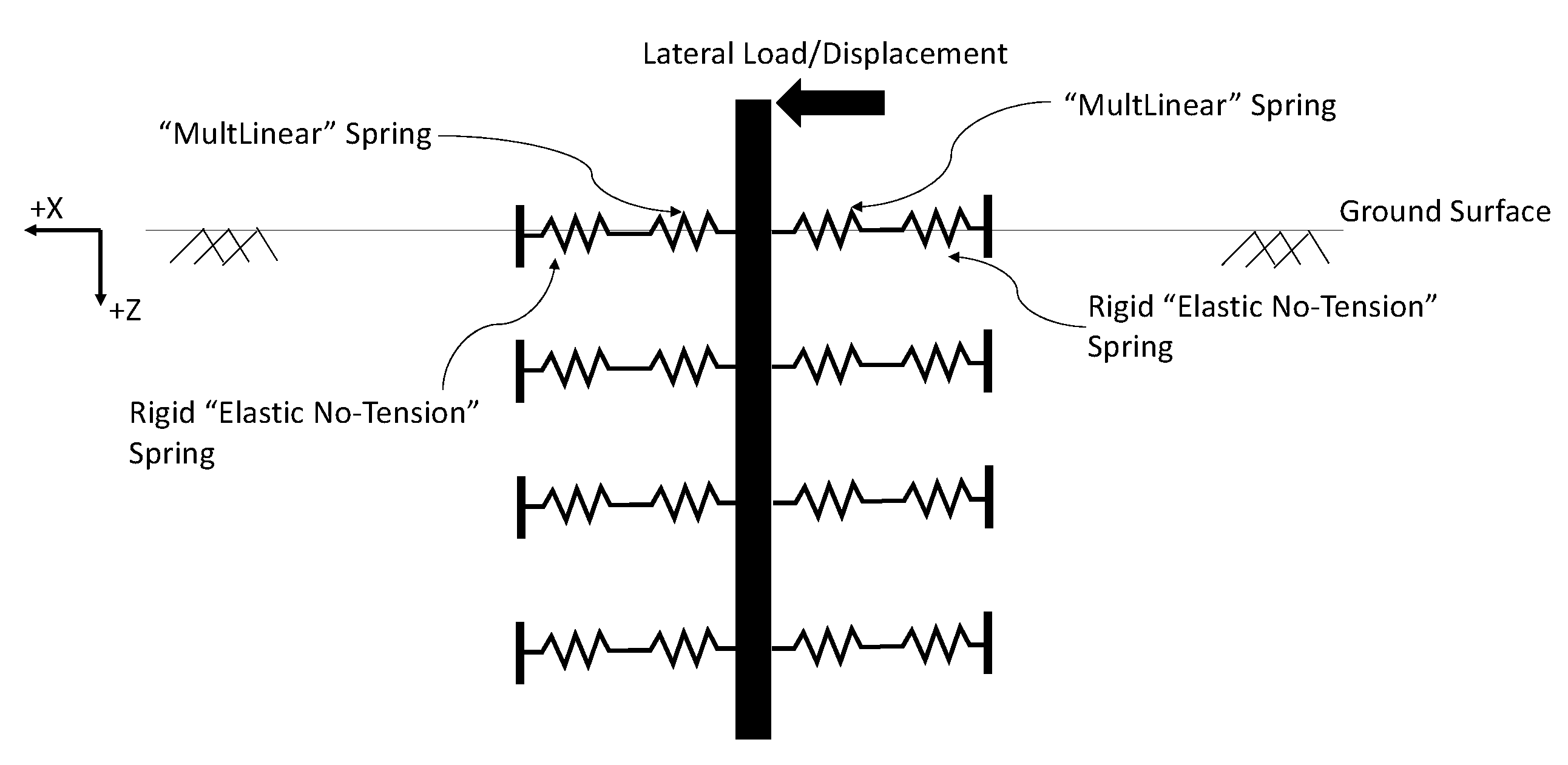
Figure 1. Schematics of the BNWF Model developed by the TCL code for Soil-Wall/Soil-Pile Interaction analysis.
The link above also includes a MATLAB code, entitled “PostProcessor.m”, that develops displacement, bending moment, shear forces, and soil reaction profiles. Please note that four parameters should be adjusted in the MATLAB code to be able to develop the graphs. These parameters are: beam total length, beam embedded length, beam element size, and the number of analysis steps that are used in the OpenSees analysis. The “PostProcessor.m” file should be placed inside the “Outputs” folder that is generated by the TCL code.
The results of the TCL code was validated by comparing the results against LPILE program for a given pile section. The pile section was considered to be a 36-inch steel pipe pile with 0.5-inch wall thickness (free-head) embedded in two soil layers. Layer 1 was considered to be 10 ft thick loose sand with effective unit Weight of 48 pcf and friction angle of 30 degrees underlain by dense sand with effective unit weight of 58 pcf and friction angle of 38 degrees. The pile was assumed to be 60 ft long with 50 ft embeddment in the ground. The pile head load of 200 kips was applied at the pile top, i.e., 10 ft above the ground surface. Figure 2 below compares the outputs of the two analyses. The results indicate that there is a good match between the OpenSees results and the LPILE results.
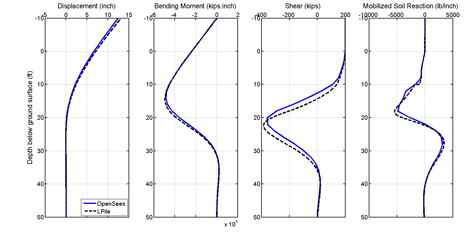
Figure 2. Comparing OpenSees against LPILE results.
Further Notes:
1. Translational and rotational springs can be defined at the pile head.
2. The TCL code can only perform static analysis for beams subjected to lateral loads.
3. If the beam is subjected to lateral pressures distributed along the beam length, the tributary load should be calculated for end nodes of each beam element and should be applied as a “Point Load” to the beam at the location of the nodes.
4. The TCL code would not develop any spring at the pile tip if the ratio of the pile embedded length (“LP_emb”) over the pile element size (“zSize”) is not an integer number. For instance, if the emebedded length of pile is 60.5 ft and pile element size is 2ft, the deepest spring would be generated at the depth of 60.0 ft.