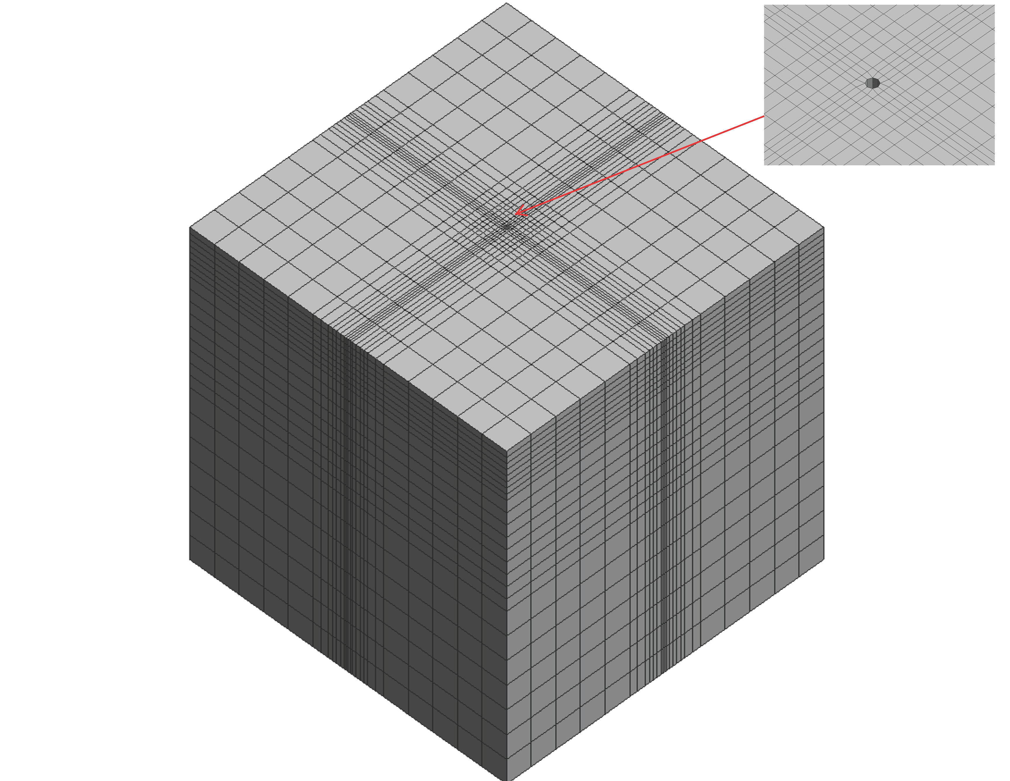
This Tcl code creates full-scale three-dimensional continuum model of single pile embedded in a layered soil profile. Soil-pile interaction including formation of gap and slippage was simulated by using the BeamContact3D element. The program is capable of performing a lateral pushover analysis on a single pile. The contact elements at the interface of soil and pile can simulate; (a) the formation of gap at the pile back face, and (b) slippage on two sides of the pile when subjected to lateral loads. Figure 1 shows the finite element mesh. This model can be used as an alternative to the conventional p-y spring approach that was previously discussed in this post.
You can download the Tcl file here: Signle-Pile-Continuum-model-Pushover-Analysis.zip
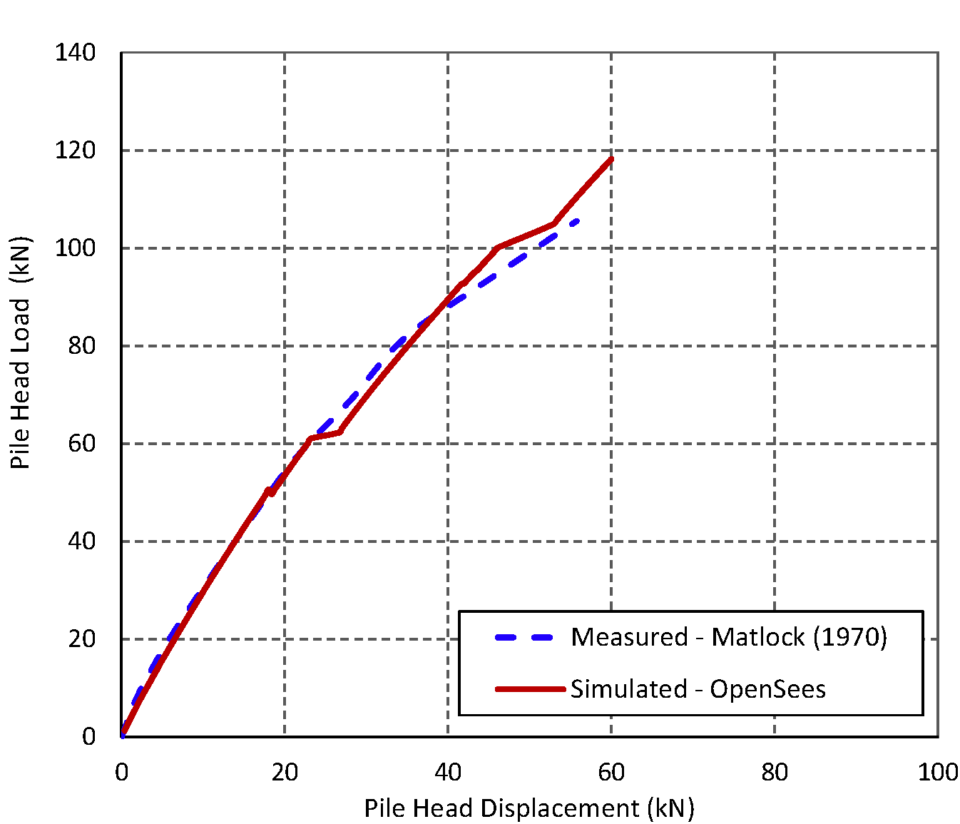
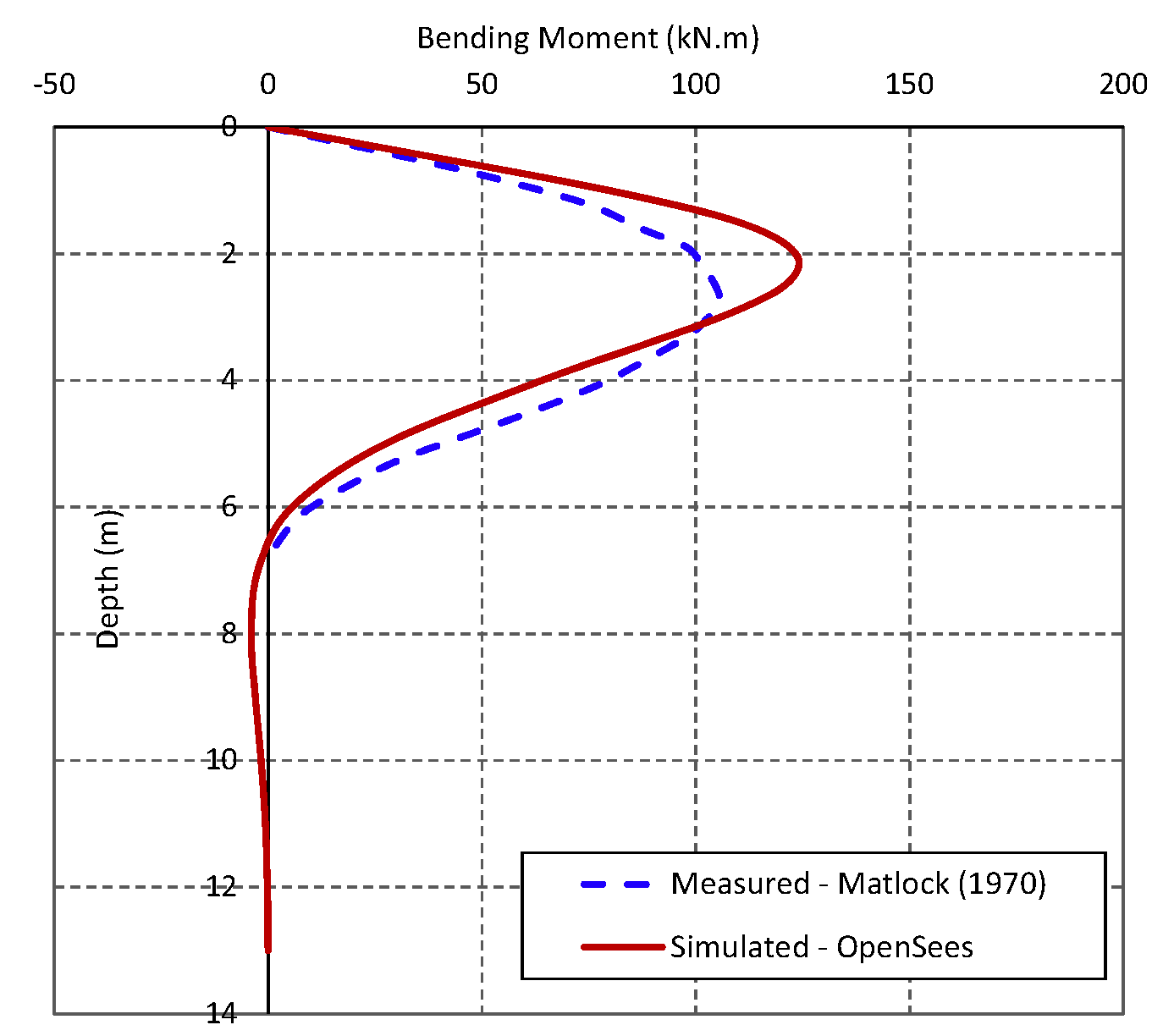
The program was validated by comparing its results against the results of the load test performed by Matlock (1970) on 32 cm diameter steel pipe pile in soft clays in Lake Austin, Texas. Further details about the test can be found in Appendix B (Test No. 11) of my PhD Thesis available in this link. Figure 2 compares the measured and simulated load-deflection curve at pile head. Figure 3 compares the bending moment profiles when a load of 80.9 kN is applied laterally at pile head. The results indicated that there is a good agreement between the simulated and measured responses implying that the OpenSees TCL code can adequately estimate pile lateral response under static loads.
Notes:
- The increase in confining pressure due to installation of pile (driven piles or any displacement pile) can be accounted for by increasing the parameter “$mu” for the contact element. For instance, per the state of practice for driven concrete piles stress increase ratio is about K/K_o= 1.25. This can be considered in the model by using the input parameter “1.25 x $mu”.
- Soil disturbance can be also modeled by applying the reduction factors (per the available guidelines) in to the stiffness and strength parameters of the contact element, i.e., the cohesion (c) and the friction which is embedded in parameter “$mu” (mu= tan \phi).
- It is recommended to use this code for lateral loading condition only. The model may not sufficiently capture deformations under axial loading.