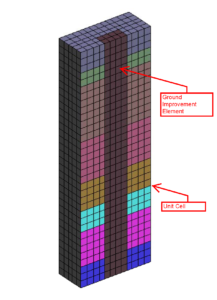
OpenSees implementation of a single ground improvement (GI) element in a continuum soil domain is described here. The Unit Cell concept is adopted to develop the ground improvement layout. The unit cell consists of a single GI element located in the center of its equivalent influence zone. The model represents a GI element located on the interior of an infinitely large group of elements. The Tcl code is capable of analyzing seismic response of a ground improvement system both in dry and saturated soils where liquefaction can be modeled. The codes are generic and can be modified for various soil domain dimensions, GI element depth and soil layers.
Note that the model is symmetric about the direction perpendicular to the direction of shaking. Therefore, in order to speed up the analysis execution time, half of the model is analyzed. Figure 1 below shows typical finite element mesh that the code can generate. Please also read the article about base boundary condition. The feature for switching into either rigid base or compliant base boundary conditions is available in the code.

To record outputs, it is important to understand how the nodes and elements have been numbered in the code. The numbering starts from 1 at (x=0, y=0, z=0) and increases with an increment of 1 in direction +Z, then when it reaches the maximum node/element, it increments in direction +Y and finally in direction +X till last node/element is reached.
To download Tcl file for dry soil condition, click here: GI_Element_Dry.zip
To download Tcl file for saturated soil condition, click here: GI_Element_Saturated.zip
Please read the notes, presented in the beginning of the code, carefully. I tried to put enough information for your use. Please write your comments below if you have any questions.
2 thoughts on “Continuum model of a single ground improvement element under seismic loading – TCL file”
hello . can I model a circular improvment element such as a circulr pile in this model ??
I want model a cicular pile with brick up element
Hi Amin, the model only considers rectangular cross sections. For circular cross-section, if you are evaluating axial capacity of the ground improvement element you can use equivalent cross-sectional area (A_cir = A_eq_rec). If you are evaluating lateral capacity you may use equivalent moment of area (I_cir=I_eq_rec).
Please also take a look at this paper. It has some useful information about using an equivalent cross-section in finite element analysis:
https://www.researchgate.net/publication/237821079_Equivalence_between_2D_and_3D_Numerical_Simulations_of_the_Seismic_Response_of_Improved_Sites