Subgrade reaction modulus is the ratio of soil pressure to deflection. This modulus is widely used in structural design of mats and slabs. The structural design is completed by structural engineer of record (SEOR) where he/she utilizes the concept of Beam on Nonlinear Winkler Foundation in order to estimate the pressure of soil as well as shear forces and bending moments induced to the foundation element. Geotechncial engineer of record (GEOR) is responsible to provide appropriate subgrade reaction modulus to characterize the Winkler springs. Appropriate estimation of subgrade reaction modulus would result in appropriate estimation of soil pressure distribution under the mat/slab which would consequently result in accurate structural design of mat/slab.
Unfortunately, there is a widespread misconception in the use of subgrade reaction modulus. Structural engineers often expect to see a single constant value for subgrade reaction modulus in soils report. However, subgrade reaction modulus is not a fundamental soil property. It is a function of (Walker and Holland, 2016):
- Geometry of loading surface area: loads with larger surface area influence deeper soil deposit that can be very soft or compressible.
- Load magnitude: soil behavior is highly nonlinear so soil would have lower subgrade modulus when subjected to larger loads.
- Soil stiffness and strength parameters as well as compressiblilty indices within the stress bulb.
- Type of loading (long term or short-term loads) for cases that foundation soil is compressible.
- Stiffness of the mat/slab which affects distribution of the soil bearing pressure.
Geometry of loading surface and type of loading must be provided by structural engineers for appropriate estimation of subgrade reaction. By former parameter, the geotechnical engineer will know to what depth stress bulbs extend, and by latter parameter, the geotechnical engineer will know whether to include consolidation in the calculation of subgrade reaction modulus or not. For example, lift-truck wheel loads (short-term loading) will cause very little, if any, long-term consolidation settlement.
Given that the above two parameters are available, let’s see how the geotechnical engineer should calculate the subgrade reaction modulus value.
1. Advanced Method (Walker and Holland, 2016):
The best approach to appropriately include the effects of all five items described above in the calculation of subgrade reaction modulus, is to analyze full-scale three-dimensional continuum model of the mat and the underlying soil domain. Walker and Holland (2016) proposed the following approach to determine subgrade reaction modulus:
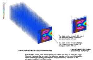
- Develop three-dimensional continuum model of the mat and the soil. Representative soil properties are assigned to the soil elements (see Fig. 1)
- Develop three-dimensional spring model (Winkler model) where soil elements are replaced by a series of one-dimensional linear elastic springs (see Fig. 1).
The spring model is analyzed iteratively by varying the spring stiffness until the computed slab pressure becomes similar to that in the continuum model. See Figure 1 below for better illustration. This may raise the question that why subgrade reaction modulus is not obtained directly from the continnum model results as the ratio of applied pressure to average of computed deformations. The reason is that the spring model has some analytical limitations. The model uses a series of uncoupled springs where deformation of one spring does not influence the deformations of other springs. In addition the springs are linear elastic while soil in the continuum model is highly nonlinear and elastoplastic. Therefore, iterative analysis of spring model is required.
Note that Walker and Holland (2016) used secant elastic stiffness for the simulation of soil behavior in their continuum model analysis; however, I personally believe that soil nonlinear elastoplastic behavior as well as soil creep behavior (consolidation) must be taken into account in any advanced geotechnical analysis. Note that since the model is nonlinear the subgrade reaction is going to vary for different load levels. If structural loads are not available, the iterative procedure discussed above has to be repeated for some typical loading levels, and subgrade reaction modulus should be provided for each load level.
2. Simplified Method
The above-mentioned iterative analysis procedure can be tedious and may require purchasing computer programs which may not be affordable for some individuals/firms. If some levels of approximation is acceptable for project design team, subgrade reaction modulus can be determined directly from a typical soil settlement analysis results. Note that it is assumed that the surface area of loading and its type (long-term or short-term) are all provided by the structural engineer.
Settle3D computer program can be used to calculate ground settlement under the given load surface area. Note that in this approach the following items are excluded from subgrade reaction calculations:
- Soil nonlinear elastoplastic response,
- Stiffness of slab/mat, and
- performing iterative analysis on spring model to ensure that stress distributions are similar.
Items 1 and 2 can be included in the calculation by performing the settlement analysis using finite element (e.g. PLAXIS) or finite difference programs (e.g. FLAC). Unfortunately, there is no way to account for Item #3 in this approach.
Concluding Remarks
Geotechnical engineers must report subgrade reaction modulus with providing some qualifiers on how the modulus should be used. It should be clearly specified that the reported subgrade reaction modulus is valid for what:
- load magnitude (e.g., 2000 psf)
- load surface area (e.g., point load or 6-foot wide storage rack)
- type of load: short-term or long-term
Some geotechnical consulting firms may report typical subgrade reaction modulus obtained from plate load test (rigid plate 12″x12″) and provide Terzaghi’s equation (1955) to modify the modulus for different foundation sizes. This approach might be appropriate for a uniform soil deposit. For a non-uniform soil deposit with interbedded compressible layers, plate load test results are NOT reliable. It is recommended to follow the procedures described in this article.
For the sake of completeness, the typical subgrade reaction modulus are listed below in Tables 1 and 2. Note that these values are valid for a 12″ plate resting on uniform soils. If there is no potential for creep and long-term consolidation, the following equations can be used in order to account for different foundation sizes (Terzaghi, 1955):
- Square Footing: k_{s}=k_{1}[\frac{B+B_1}{2B}]^2
- Rectangular Footing: k_{s,rect.}=k_{s}\frac{(1+0.5B/L)}{1.50}
- Continuous Footing: k_{s,cont.}=0.67k_{s}
where k_{1} is 12″ plate subgrade modulus, B_1 is plate width in the load test (typically 12″), B is foundation width, and L is the rectangular footing length.
Table 1. Typical subgrade modulus for a rigid plate 12 inch in diameter.
Ref: Lindeburg – Civil Engineering Reference Manual (15th Edition)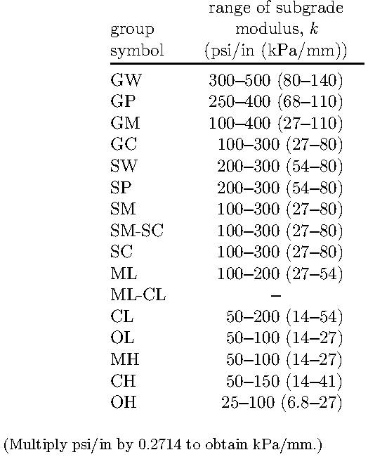
Table 2. Typical subgrade modulus for a rigid plate 12 inch in diameter.
Ref: Principles of Foundation Engineering – Braja M. Das (8th Edition)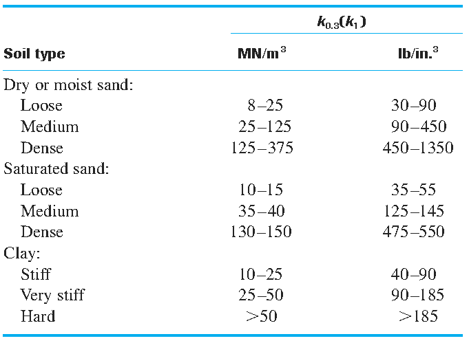
As noted in the table the subgrade reaction modulus varies in a wide range for each soil type. It is highly recommended to follow either of approaches 1 or 2 as described in this article to determine subgrade reaction modulus.