Long-term consolidation, seismic dry sand and liquefaction-induced settlements of a soil deposit can impart significant amount of downward load to piles. This load, called downdrag or negative skin friction, is caused by the friction between the pile and the downward moving soil.
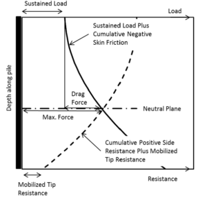
In my previous post (click here), I explained how to calculate downdrag load based on guidelines of AASHTO LRFD Bridge Design (2012). You noted that in the AASHTO approach pile compression due to structural loads plus downdrag force was not accounted for in the calculation of soil-pile relative displacement. In that approach, soil-pile relative displacement was just the free-field soil settlement equal to or greater than 0.4 inches. This drawback is resolved in the Neutral Plane Method where a plot of “pile head load + negative skin friction” is compared against a plot of “positive skin friction + mobilized pile tip resistance”. This is illustrated in the Figure 1 below. Neutral plane is the location where the two profile of pile forces intersect. This location is also where relative movement between the pile and surrounding soil is zero.
The pile head load should NOT be factored (service load type), and it should represent sustained structural loads which is typically dead load plus some percentage of live load. You should check your local building code to find out what percentage is required. As discussed in my previous post (click here), per ASCE 7-10 (United States), the percentage for long term loads is 50% so sustained load would be D+0.5L.
Generic t-z and Q-z curves are required to calculate positive friction and mobilized pile tip resistance as a function of soil-pile relative movement. An iterative analysis should be carried out which involves assuming a mobilized tip resistance and then determining its compatibility with the loads mobilized along the pile as well as the pile head load (Siegel et al. 2014). I have incorporated this iterative process in separate spreadsheets for drilled shafts and driven piles. You can download the files from the links below. Before using the spreadsheets you need to;
- Compute soil settlement profile in the free-field;
- Determine a generalized soil profile with soil properties such as cohesion, friction, N60 (for drilled piles in sands), and unit weight.
Note that ultimate skin friction and ultimate end bearing capacity are determined based on the guidelines of AASHTO LRFD Bridge Design (2012) – sections 10.7 and 10.8. The code uses the t-z and Q-z curves outlined in American Petroleum Institute (API). In case you have a site-specific curves you can incorporate the formulations into the macro Functions “Q_z”, t_z_Clay”, and t_z_Sand”.
You can download the Excel Spreadsheet for analysis of drilled shafts here:
Downdrag_Drilled-Shafts_Neutral-Plane.xlsm
(last updated: 05/04/18)
You can download the Excel Spreadsheet for analysis of driven piles here:
Downdrag_Driven-Piles_Neutral-Plane.xlsm
(last updated: 03/11/18)
Please read the “Notes” carefully before using the spreadsheets.
Some additional notes:
- The macros calculate; (i) downdrag force, (ii) pile post-consolidation/post-earthquake settlement, and (iii) neutral plane depth.
- Free-field soil settlement profile can be input directly from Settle3D, CLiq, etc. There is no need to modify the data. The macro will automatically incorporate appropriate depth and settlement into calculations.
- In case the analysis failed to converge, please try either of the followings:
- increase the allowable load difference in cell “D41” in Drilled shaft spreadsheet and “D46” in driven pile spreadsheet. This load is the difference between computed load for a given pile tip displacement and the user-defined sustained load at pile head. In my opinion a value of up to 10 kips is acceptable.
- if the load is too high for a given column depth, the code may fail to converge because of insufficient bearing capacity. In such cases, you need to either reduce the sustained loads or increase pile depth.
Write comments if you have any questions.